Build
Your Own Arcade Controls

The following write-up
explains how to convert a control panel from an Atari Return of the Jedi
machine so it works on a standard PC gameport.
If you would rather
build a USB yoke, there is an alternative hack availablesee the FAQ at
the end of this document for details.

(Click
for a larger view)

Episode
I: GETTING THE DARN THING OPEN
"I already
tried, it's magnetically sealed!"
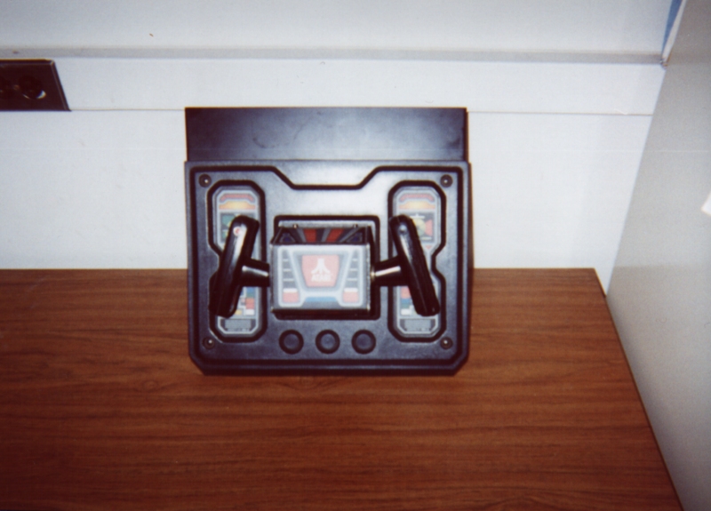
Before starting work
on the flight yoke conversion, you need to gain access to the inner workings
of the controller. This means you have to take off the front face
plate (the part that says Atari on it). This plate is held in place
with 4 pesky security type Allen head screws. The ones on my controller
were 3/32 inch hex, which means you need a 3/32 inch ball driver or Allen
wrench to get them off. If you can find a set of the security Allen
wrenches, more power to you. I received only strange looks at the
local hardware stores, so I had to take more drastic measures. If
you find yourself in the same situation, you'll have to drill the little
posts out of the bolts before unscrewing them. Use a power drill
for this (or a milling machine if you have access to one). Be careful
while drilling, or you'll wear down the edges and won't be able to get
the screws out. (I ended up replacing my screws with standard machine
screws--if you want to do the same thing, buy screws with a 6 - 32 thread.)
Once you have the screws off, you're ready to swap in some components.
(Click
for a larger view)
 (Click
for a larger view)
(Click
for a larger view) |
 (Click
for a larger view)
(Click
for a larger view) |
Episode
II: Swapping The Potentiometers
"Sir,
if any of my circuits or gears will help I'll gladly donate them!"
My hat goes off to
those fine folks at Atari for building such a modular controller.
What you need to do now is remove the original potentiometers (pots) from
the controller. It turns out that the potentiometers that Atari used
were of the 5 k Ohm variety, while modern PC joystick ports require pots
in the realm of 100 to 150 k Ohm. Fortunately, the original potentiometers
were of the standard style, and replacements that fit are easily found.
A brief word about
selecting substitute potentiometers:
Use linear, not
audio taper pots!
I bought two new
potentiometers at radio shack--namely 100 k Ohm linear taper pots.
It is important to note that you must purchase LINEAR potentiometers in
order to do this project. You will know linear pots by the stamped
label B100K. The B denotes a linear resistance responsehalf
of the full turning range will be 50 K Ohm. Stay away from audio
taper pots, which are marked A100K, because the resistance curve
for these potentiometers will give you funny (exponential!) control
when using your yoke! Here is the information from the Radio
Shack catalog:
100K Ohm Linear Taper
Potentiometer
Model #: 271-092
Price: $2.79
These pots fit perfectly
into the mounts on the controller and have shafts that are long enough
to reach the plastic gears (this is critical!). An important consideration
when purchasing pots is getting ones with the correct number of turns.
The Radio Shack model listed above is a 100 K Ohm, 3/4 turn pot.
This means that 3/4 of a turn (270 degrees) gets you up to 100 K Ohm resistance.
This is how the original Atari potentiometers worked (except they went
to 5 K instead of 100 K). You can use pots with bigger values and
more turns, as long as you go from 0 to 100 K Ohm resistance over
the course of 3/4 of a turn. (i.e. a 1.5 turn, 200 K Ohm pot would
fit the bill)
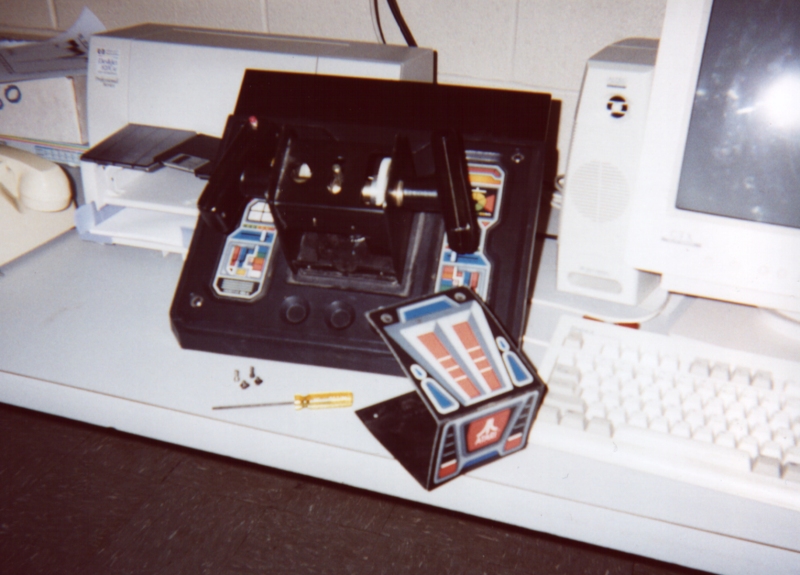
There are two pots
in the controller, one that drives the vertical axis (inside the front
panel you removed in Episode 1) and one that drives the horizontal axis
(on the back side of the control panel). The first thing you'll want
to do is remove the plastic gears that are attached to the potentiometers.
This job requires a 7/64 inch ball driver (or Allen wrench). Loosen
the bolt, and slide the gear off the shaft. Now you need to remove
the potentiometers from the mounts in the panel. You'll need to use
an adjustable wrench to take out the potentiometers--they are held in place
by nuts that are coaxial with the shaft. You can now clip the wires
(3 per pot) and remove the pots. Save the pots in case you ever want
to convert the controller back to its original state or go the USB hack
route (see the FAQ below).
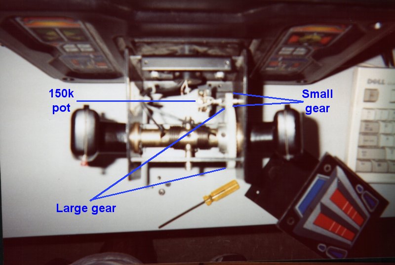
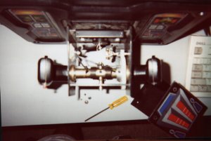
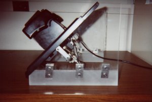
| Top view, yoke interior:
The big plastic gear
drives the smaller gear above it, which is attached to a 3/4" turn , 100k
Ohm potentiometer (Y axis).
(Click picture for
labeled details) |
 (Click
for a larger view)
(Click
for a larger view) |
Now it's time to
put those new pots in the controller. For the one going inside the
front panel, you'll probably have to cut the shaft so the thing will fit
inside (if you're using the same pots I bought). Just put the shaft
end in a vice and cut it to length with a hacksaw or dremel tool.
After cutting the shaft, place the pot in the same position as the original
pot. Replace the nuts and washers to insure a snug fit. Do
the same for the X axis pot.
What you need to
do now is make sure the pots are centered. If you have access to
a multi meter, set it to measure resistance (Ohms) and dial each of your
potentiometers until the meter reads 50 K Ohms. Once the potentiometers
are centered, replace the gears, insuring that the teeth of the small gears
are interlocked with the teeth of the big gears. Now, without turning
the shafts of the potentiometers, tighten up the bolts on the shafts attached
to each of the small plastic gears. Once you have tightened the gears,
check the resistance of the potentiometers. They should read roughly
50 K Ohms while the mechanical axis in question is at its spring-centered
point. If youre not reading 50 K Ohms, loosen the gear in question
and repeat the procedure outlined above until 50 K Ohms is reached.
Make sure each axis is set so the controller is limiting the range of motion
(by those heavy metal stops and posts) on the far left/far right (or far
up/far down) positions. If the pot the limiting factor in the motion,
you won't be getting full motion onscreen during game play (and you might
break the pot if you torque the controller too hard!). You may need
to revisit this process later for fine adjustment. Now that everything
is in place, it's time to do some wiring and soldering!
 (Click
for a larger view)
(Click
for a larger view) |
 (Click
for a larger view)
(Click
for a larger view) |
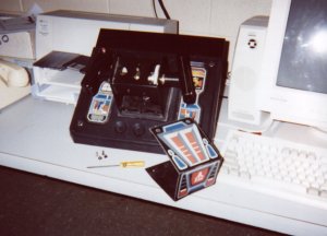
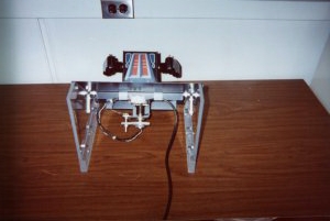
| Inside
the controller |
Episode
III: Wiring
"This
one goes there, that one goes there!"
Now that all the
hardware has been swapped, it's time to wire the controller up to the joystick
port. It would be a good idea to get a hold of a multi meter to test
the pots. You only need two wires coming from each pot (rather than
the 3 that the Atari protocol uses). Solder one wire to the middle
pin on each pot, and one wire to each leftmost pin. (The word 'leftmost'
doesn't matter much here, since you can reverse joystick axes in most emulators.)
To test a pot, connect a multi meter to the two wires and turn the pot.
You should get a resistance range that goes from 0 to 100 K Ohm (if you
bought a standard 3/4 turn 100 K pot). Send the wires for the vertical
axis through the yoke (where the factory wires are going). If you
want, you can use the original wires for this purpose--you'll just have
to find them on the insulated connector coming out the back. I opted
to use my own new wires. When you're done with this step, you should
have 4 wires coming from the pots.
Now it's time to
get some wires set up for the fire buttons. If you want, you can
use the factory wiring, and avoid opening up the handgrips entirely.
To do this, youll have to press the buttons and search for connections
with a multi meter. (On a Jedi controller, the triggers are white
wires, the push buttons are red wires, and they all share a common ground,
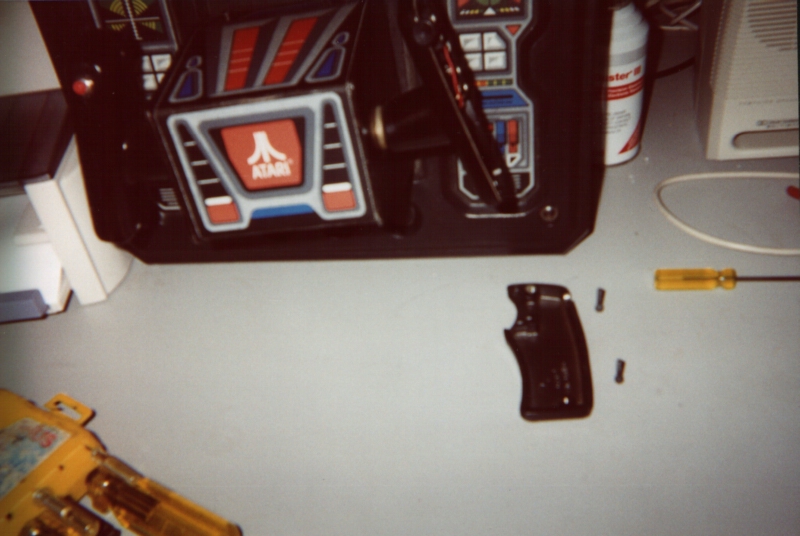
which goes to some black wires.) For direct tracing of the
wiring, you can gain access to the buttons by using a 7/64 inch ball driver
to open up the handgrips. After removing the two screws (thankfully
they aren't the security type!) simply remove the handgrip shells.
Be careful not to loose the little springs connected to the triggers/buttons--they
have been planning an escape for a long time! The switches utilized
for the fire buttons are the small microswitch type. In each grip
you will find that the trigger (white wire) and push-button (red wire)
share a common ground (black wire). Again, use the multimeter to
figure out where the switch wires end up on the other side of the yoke--I
opted to use the factory wires for my firing buttons, but again, you can
wire your own if you want to. If any of your buttons, springs, or
switches are mangled, they can be replaced. There are often people
selling replacement parts for Atari yokes on Ebay or in the arcade newsgroups
on Dejanews.

(Click
for a larger view)
I recommend purchasing
a 6 foot joystick extension cable. An extension cable is a good way
to go because it contains a discrete wire for each pin (15 of them) on
the joystick port. This will enable you to run up to 4 discrete buttons
on your yoke. (you need 3 discrete buttons for Return of the Jedi!)
These extensions run around $14 or so and can be picked up at most computer
stores. Remove the female end of the cable with a pair of wire cutters
(leaving the male end to plug into your game port) . Using a razor
blade or utility knife, carefully slice open the cut end of the cable to
expose the wires within. There should be 15 wires, and if you're
lucky, the manufacturer used different colors for each of them. A
wire stripping tool is a must have in this situation. Now you need
to figure out where to connect all of these little wires.
There are some excellent
resources on the web describing the functionality of the game port.
Here's a pinout
for the joystick port..I got this from:
http://www.hut.fi/Misc/Electronics/docs/joystick/pc_joystick.html
What a great site!
_______________________________________________
\
8 7
6 5
4 3
2 1
/
\
9 10
11 12
13 14
15 /
` -----------------------------------------------------------------------'
This
will quite likely look funny in your browser due to reformatting...
1 XY1 (+5v)
2 Switch 1
3 X1
4 Ground (switch
1)
5 Ground (switch
2)
6 Y1
7 Switch 2
8 Nothing
9 XY2 (+5v)
10 Switch 3
11 X2
12 Ground (switch
3,4)
13 Y2
14 Switch 4
15 Nothing
Ok, keep in mind
that some game cards use the pins a little differently (in case things
are really going awry!). This pinout hasn't done me wrong yet
though. See the site I referenced above for more details, or some
of the excellent resources on John St.Clair's controller
site. For this project, pins 1,2,3,4,6,7 and 10 will be used.
This gives us X,Y control and three buttons. (You can wire up the
fourth button if you want to.) Now it's time to connect the yoke
wires to the joystick extension wires. I suggest a temporary setup
first to troubleshoot things, followed by a permanent connection when things
are 100% working.
| Fire
buttons first (3 button setup) |
|
|
|
 |
Connect the two
white joystick trigger wires (traced to the molded connector with a multimeter)
to pin 2 (Switch 1). |
|
Connect one red
joystick button wire to pin 7 (Switch 2), and the other to pin 10 (Switch
3). |
|
Connect the two
black joystick ground wires to pin 4. On my controller, it was ok
for all of the switches (1-3) to share the same ground. |
| X
control |
|
|
|
|
Connect one wire
from the X pot to pin 3 (X1). |
|
Connect the other
wire from the X pot to pin 1 (+5 V). |
| Y
control |
|
|
|
|
Connect one wire
from the Y pot to pin 6 (Y1). |
|
Connect the other
wire from the Y pot to pin 1 (+5 V). |
If you want to, you
can use the +5V source at pin 9 for either X or Y control if it makes for
more convenient wiring. I ended up using a couple of 12 pin molded
nylon connectors (from Radio Shack) to make the connections. You
can make tidy connections with this connector, and reuse that joystick
extension cable for other projects. Now you're ready to plug the
controller into your computer and test it out! Make sure you don't
have any dangling exposed wires coming from the joystick port--if the +5
V wires ground out, they can generate a lot of heat!
Epilogue:
"No
more training do you require.. already know you, that what you need.."
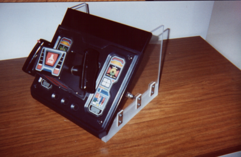
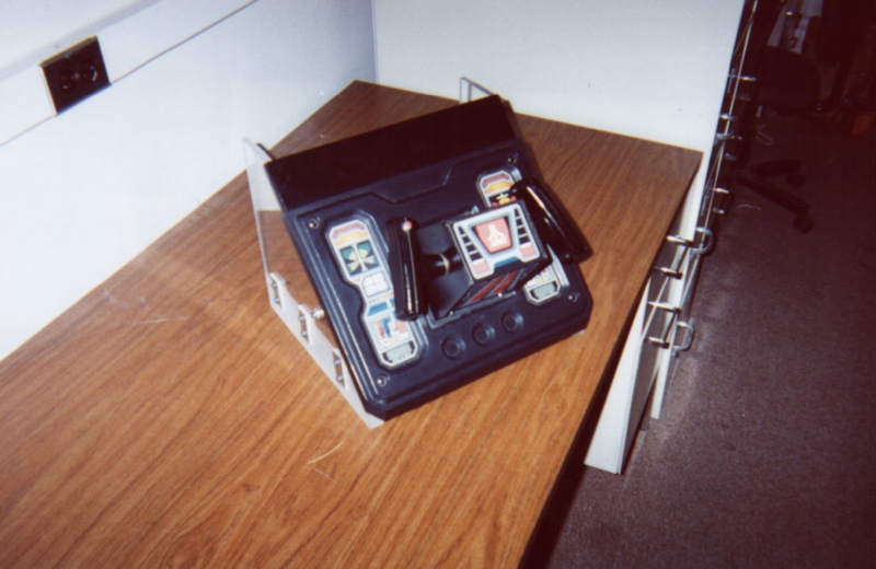
Now that you have
finished the wiring, you still need to mount the control panel to something.
If you have an old neglected cabinet handy, go for it! If not, you
can fashion a case for the controller yourself. I ended up making
a desktop case out of plexiglass. The plastic piece on the front
of the control panel easily unbolts, giving you access to the bare sheet
metal below. This allows you to mount the control panel in any fashion
you see fit. I could go into some more details about the case I built,
but I'll leave that story for another day! If you have any comments,
questions, or suggestions, feel free to contact me via email.
Frequently
Asked Questions:
Where can I get a Star Wars yoke controller?
Where can
I get a Star Wars yoke controller?
This is by far the
most frequent question I have received over the years. The short
answer is Ebay--thats where I found mine. Also, you might want to
snoop around the arcade newsgroups on Dejanews---they are always selling
arcade parts. You should keep in mind that there are a few other
less well known games produced by Atari that used yoke controllers.
S.T.U.N. Runner and Hydra both use the same style yokes found on the Star
Wars machines. When looking for yokes on Ebay, you might want to
consider a broken yoke, or one that is missing its wiring. These
go for a lot less that pristine yokes, and youll have about the same amount
of work to do either way!
How much do
yokes cost?
Well, I have seen
them go for as little as $25 for a dinged up yoke, all the way up to $150+
for a beautiful looking yoke NOS yoke. I think $100 is pretty typical
these days.
Sometimes I
have to recalibrate my yoke when going from one game in MAME to another..
why is this?
Well, I think it
has to do with the way some games are emulated in MAME. This may
have changed by now, but some games just see the joystick a little differently
than others. Your best option is to recalibrate when this is the
case, and leave the joystick calibrated for the yoke game you use most
often!
Windows isnt
finding my joystick.. why?
Its probably because
you have a bad connection going to one of your potentiometers. When
Windows looks for a joystick, it is looking for current running from
the +5 V pin of the game port to BOTH the X and Y axis pins. If this
isnt happening on both pins, Windows will not acknowledge the presence
of a joystick. Windows doesnt care about the button connections
when looking for joysticks, so keep this in mind. Windows may tell
you that the joystick is connected and functioning properly without knowing
that you missed a button wire.
Are there any
other yoke hacks out there I should check out?
Yes! 1UP has
put together an alternative method--take a look at: http://www.1uparcade.com/
His hack is USB compatible, as it is based on Microsofts Dual Strike controller.
It is an excellent hackI have tried it myself and it works like a charm.
Which hack
works better, Judes game port yoke hack or 1UPs USB yoke hack?
I have built and
compared both hacks, and I can say that (on my machine) 1UPs USB hack
provides smoother control than the joystick port hack. My guess is
the Dual Strike has better resolution on its analog to digital converters
than the PC game port does. 1UPs hack also has the added advantage
of USB compatibility, and mouse functionality to boot! Still, the
old joystick hack does have some advantagesit may end up being a little
bit cheaper (depending on how much you pay for a Dual Strike), and will
work well if youre setting up a MAME rig based on a DOS platform or an
older PC that doesnt accommodate USB.
Best of luck with
your projects!
-Jude A. Kelley,
10/28/03
--
Home --